Alternatively, you can contact us like this:
Technical Centre
Application Related FAQ
Select question from the list below.
-
What is a traditional distributed power solution?
Traditional designs that employ distributed power architecture place DC-DC converters on PC boards very close to the point-of-load to maximize system speeds and efficiencies. To power the DC-DC converters, the required AC-DC power supply with PFHC is typically mounted somewhere in the system's enclosure, external to the main pc-board (Figure 1). This technique is quite reasonable for most applications. However, when it comes to equipment that must be mounted outdoors and occupy the smallest possible volume, there are now improved power products available.

-
What are the types of Distributed Power Architectures?
Compact DC-DC converters have made their way into millions of electronic products and systems. The vast majority of these depend upon an AC front-end-box to convert the AC power source into a DC voltage from which the converters operate. In addition, international regulations have mandated that these front-end-boxes include Power Factor & Harmonic Correction (PFHC) to maximize the available power from the power grid.
-
How have power distribution methods improved?
Typical medium power (400-700 watts) PCB mounted DC-DC converters are packaged in "full brick" sizes (e.g., 2.4" W x 4.6" L x 0.5" H). A number of major manufacturers of DC-DC converters have seen the need for, and are now providing AC input PFHC front ends in brick-formats that are PCB mountable near to the DC-DC converter(s). This has the advantage of placing all the power components on the same pc-board thus reducing the end products size and eliminating the power interconnect wires (Figure 2).
These AC-DC w/PFHC front-end bricks require some external components (capacitors, resistors, etc.), but the space required for these items is small in comparison to the elimination of the external "metal boxed AC front end". And, these external components can be robotically inserted during the production of the pc-board. An added benefit of utilizing these brick packages is that they can be cooled without fans, by means of heat sinks or cold plates (e.g., mounting the brick bases against the system’s metal enclosure).
-
Why is there a need for redundant power supplies?
Imagine a 24Vdc 10A power supply driving motors and sensors on a conveyor based production line. For two or three years everything works fine, then one Friday (always at the end of the month), the power supply fails causing the conveyor to stop. Even if a spare part is in stock, it could still result in 30 minutes of expensive lost production.
If two identical power supplies had been installed in a fault tolerant, redundant mode, the remaining (good) unit would have continued to power the production line. The failed power supply could then be replaced at a more convenient time during routine maintenance.
-
What Frequently Used Terminology is used for redundant power supplies?
N+1
An expression where N is the number of power supplies needed to run the system. The simple two power supply system mentioned above would be considered 1+1. A triple redundant system (where two failures would have to occur to shut the system down) would be designated 1+2.
Hot-swap
Some equipment is operated 24 hours a day, 7 days a week, allowing no time to bring the system down for maintenance. In this case the failed power supply must be “swapped” out and a new one inserted without disruption to equipment operation.
ORing diodes
In the rare event of a power supply failing with a shorted output, low voltage-drop ORing diodes block that short from bringing down the system power.
Current share
Some power systems employ a method of balancing the current between the power supplies to increase field life. This can be an electronic signal wire that links the power supplies together or a switch* on the power supply that initiates a slight drop in the output voltage as more current is drawn. (*Common on high power DIN rail units)
-
How do you implement Fault Tolerance?
DIN Rail mount
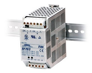
For the example listed above, the simplest off-the-shelf solution is to use a diode "ORing" module and two power supplies. Here we are using TDK-Lambda's DIN rail mount DLP-PU module and two 24V 10A DLP240-24-1/E power supplies. (/uk/dlp)
Tip: When wiring the system, ensure that the cable lengths from the output of the power supplies to the ORing module are equal. This will help optimise the performance and life of the power supplies. See Figure 1 below.
Inside the diode ORing module are two diodes and two alarm relays. Even in the event of one power supply failing with an internal short circuit, the remaining unit will continue to deliver power. See Figure 2 below.
Tip: - It is important to identify power supply failure using the relay alarms to flag the need for maintenance. Engineers sometimes overlook this which can result in a second failure unexpectedly bringing the system down!
Rack Mount
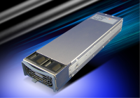
System Engineers requiring more power are turning to the communications style racks. These sophisticated low cost systems allow power supplies to be hot-swapped and come completely self contained. An example of such a product is TDK-Lambda's HFE series. (/uk/hfe)
Advantages of this solution include:- Easy mounting into a standard 19" rack
- All in one solution
- Hot swap capable (ORing diodes or MOSFET switches built-in)
- No tools are required for replacement of a supply
- High density, low profile (1.75")
- Off the shelf parts
- Fully safety approved
- All necessary warning signals included
- 12V, 24V, 32-36V and 48V outputs
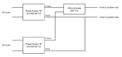
Figure 1
ORing module
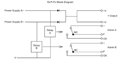
Figure 2
HFE series
-
What are the key differences between Conduction, Convection and Radiated Cooling?
All power devices generate heat. This is due to the unavoidable internal losses of all power circuits due to their inefficiencies. The higher the efficiency rating of the power device, the less internal heat is generated within it. If we could achieve 100% efficiency, there would be no heat generated within the power device and no cooling required.
There are three methods of transferring or removing heat from power devices: These are conduction, convection and radiant. In all cases, the heat is being transferred from the power device to another medium that is at a lower temperature. Heat is constantly seeking to move to any object or medium that is cooler.
Conduction Cooling: This is defined as the transfer of heat from one hot part to another cooler part by direct contact. For example, many DC-DC converters have a flat surface that is designed to mount directly to an external heat sink or cold plate that will conduct the heat away from the power device by direct contact, thereby cooling it. Conduction is the most widely used method of heat transfer. All power supplies use internal heat sinks to help conduct the heat away from the hot devices.
Convection Cooling: This involves the transfer of heat from a power device by the action of the natural air flow (a low density fluid) surrounding and contacting the device. Many power devices are rated for natural convection cooling as long as the air surrounding the unit remains within a limited temperature range that is cooler than the device. The advantage of this method of cooling is that no electromechanical fans are required.
Another type of convection cooling requires forced-air-flow via fans or blowers across the power device. Many power supplies come with a build-in fan to provide this forced air type of convection cooling. Other types of power supplies specify the amount of air flow that must pass through or around the device (in cubic-feet-per-minute) in order for the supply to provide its maximum rated output power.
Some power devices with heat sinks depend on convection cooling (with or without forced air) to assist in transferring the heat away from the power devices to the cooler air.
Radiated Cooling: This is the transfer of heat by means of electromagnetic radiation (energy waves) that flow from a hot object (power device) to a cooler object. True radiated heat transfer can take place in a vacuum and does not require air. It should be noted that conduction cooled power devices also give off radiated heat; however, radiant heat transfer is less effective as a means to cool a power device than are conduction or convection cooling described above.
-
What is Droop Mode Current Share?
If two power supplies are to be connected together to produce more power or share the load, then a parallel capable model should be selected. TDK-Lambda's DPP100, 120, 240 and 480 models are all parallel capable. On the front of each power supply is a small black switch. For parallel operation this switch should be set to "parallel" (Fig. 1). (/uk/dpp)
In single mode the load regulation (the amount the output voltages chances with load) is minimal, the difference being less than 0.24V from zero load to full load for a 24V output power supply.
In parallel mode that load regulation is artificially increased to 1.2V using internal circuitry (Fig. 2).
The extra voltage drop or "droop" is proportional to the load drawn, so that when two or more power supplies are connected in parallel the output load is shared between the power supplies. If on of the paralleled power supplies tries to provide more current, its output will droop slightly and the other supplies will balance.
For optimal performance, all power supplies should have their outputs set to the same voltage.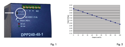
-
What is Remote Sensing?
Most medium to high power AC-DC power supplies and DC-DC converters have “Remote Sense” connection points (+/- Sense) that are used to regulate the supply's output voltage at the load. Since the cables that connect a power supply's output to its load have some resistance, as current flows it will cause a voltage drop in the cables. Since it is best to regulate the voltage at the load site, the use of the two Remote Sense wires connected from the supply to the load will compensate for these voltage drops.
Typical remote sensing circuits are capable of correcting from 0.3V to 1.0V of voltage-drop in the output cables. However, to be sure, always check your power supply’s instruction manual to determine the maximum remote sense compensating range. If the voltage drop across the cables exceed the range of the remote sense circuits, this can be remedied by either reducing the length of the cables or increasing the size of the cable’s conductors. The remote sense leads carry very little current, so light gauge wires can be used. Steps should be taken to ensure the remote sense wires do not pick up noise by either twisting the +/- Sense wires together and/or shielding the wires from noise. It is important to observe the correct polarities, i.e., the +Sense wire should connect at the load to the +V output cable and the –Sense wire should connect at the load to the –V output cable. Refer to Figure 1.
When not using the remote sense feature, Local Sense (LS) connections should be used. In this case the +/-Sense points should be connected to their corresponding output or local sense terminals at the power supply (+Sense to +V output or +LS and, –Sense to –V output or -LS). Most power supplies are shipped from the factory with these "Local Sense" connections in place. Refer to Figure 2.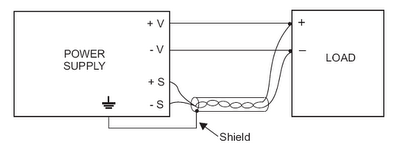
Fig. 1: Power Supply with Remote Sense Wires Connected at the Load
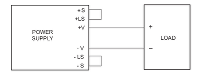
Fig. 2: Power Supply with Local Sense Jumpers Installed
-
Why do Power Supplies have Wide Range Adjustable Outputs?
For some power supply applications it is desirable to change the output voltage over a wide range. There are a number of ways to control the output voltage of power supplies that are designed to provide wide adjustment ranges. Remotely adjustable output voltages can be implemented by using one of the following methods.
Variable Voltage Control In this case an external variable control voltage (e.g., 1-6V) is connected to the designated input of the power supply, sometimes called the PV input. As the input control voltage is varied it will cause the output voltage to change in a fairly linear fashion over a wide range (e.g., 20% to 120% of the nominal output voltage). For some applications this is a low cost method of providing a programmable power supply. Below are diagrams showing an example of this type of remote voltage adjustment for TDK-Lambda’s HWS/PV (/uk/hws) and SWS-L series (/uk/sws) of power supplies.
Variable Resistive Control Some power supplies can be remotely adjusted via a variable resistive control (external potentiometer). This method has the advantage that an external voltage is not required since an internal Ref. voltage is provided by the supply. As the resistance changes, it will cause the output voltage to change in a non-linear fashion over a wide range (e.g., 20% to 120% of the nominal output voltage) as shown in the diagrams below (TDK-Lambda’s HWS/PV series). For some applications this is a low cost method of providing a programmable power supply.
Serial Digital Control Programmable Power Supplies can be remotely controlled via a serial digital port such as RS232 or RS485. Both the output voltage and current can be controlled from zero to the maximum output ratings. In addition, alarm signals from the supplies can be sent back to the remote computer or controller via the same digital link. Programmable Power Supplies are more expensive than wide adjustable supplies mentioned above, but they have a large array of local and remote control features that are not found elsewhere. TDK-Lambda’s ZUP series is a good example of a feature-rich Programmable Power Supply.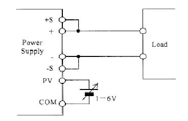
External Variable Voltage Control (1-6V)
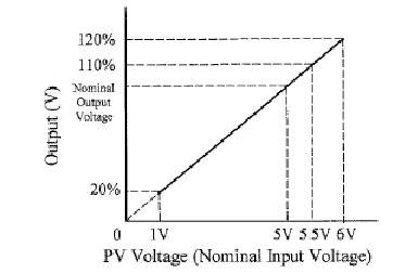
Output Voltage Change (20-120%) with Ext. Variable Voltage Control (1-6V)
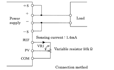
External Variable Resistive Control (50k ohm pot.)
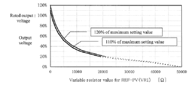
Output Voltage Change (20-120%) with Ext. Variable Resistive Control (50k ohm pot.)
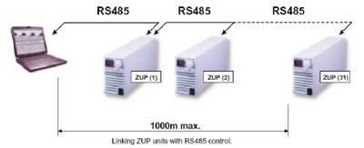
Up to 31 ZUP Series Programmable Supplies can be Remotely Controlled via RS485 Interfaces
-
What is Over Current Protection (OCP) and why do Power Supplies & Converters need it?
Most AC-DC power supplies and DC-DC converters have internal current-limiting circuits to protect the power device, and to some degree its load. The majority of over-current-protections include an automatic recovery feature. In practice, the current limit feature typically starts operating when the output current exceeds it maximum rating by 10 to 20%.
In many cases, should an overload (e.g., short circuit) be allowed to exist for a prolonged period, it can reduce the product’s field life by temperature stressing the electrolytic capacitors, and in extreme cases, it can damage the user’s printed circuit traces. Therefore, always check the power supply’s “Instruction Manual” to be sure you understand the precautions associated with the power product’s over-current-protection feature. Also, if the power product has an Output Good signal, this can be used as an indication that the power supply is either faulty or could be in an over-current mode.
There are a number of ways to implement over-current-protection (OCP), and below are descriptions of the most common methods.
-
Why you need to know the maximum remote sense compensating range
Most remote sensing circuits are capable of compensating for voltage drops across the output cables of between 0.25V and 0.75V. However, to be sure, always check your power supply’s instruction manual to determine its maximum remote sense compensating range.
If the voltage drop across the output cables exceeds the compensating range of the remote sense circuits, the voltage at the load will no longer be regulated. This problem can be remedied easily by either reducing the length of the output cables or increasing the size (heavier wire gauge) of the output cables to reduce the excessive voltage drop.
Remember, voltage drop should always be kept to a minimum and the reason why is simple – a 0.5V voltage drop to a 100A load, translates to 50W lost power in each cable, or a total power wastage of 100W.
-
Why you need to know the adjustment range and OVP set-point
The remote sense function automatically increases the output voltage at the output terminals of the power supply to compensate for any unwanted voltage drop in the output cables with heavy load currents. Likewise, the remote sense function decreases the output voltage of the supply when the required load current is reduced.
In some applications, the power supply’s output needs to be adjusted by the user to a voltage higher than its nominal (e.g. 5V nominal, adjusted to 5.5V).
Always adjust the power supply’s output, while measuring the voltage at the load. In addition, care should be taken to assure that, while under full load, the remote sense function does not push the Vout to a higher voltage as this could possibly trip the OVP set-point and shutdown the supply.
To find out the power supply’s adjustment range and OVP set-point, read the instruction manual.
-
How to avoid picking up radiated noise on the remote sense wires
The remote sense leads carry very little current, so light gauge wires can be used.
However, steps should be taken to ensure that the remote sense wires do not pick up radiated noise – this can be achieved by:
1. twisting the +ve and -ve sense wires together
2. shielding the wires from the noise
TIP: It is best to use different coloured sense wires (e.g., black and red) so that after they are twisted it is easy to determine which wire is the +ve and -ve sense.
-
Ways to avoid cross-connection of remote sense wires
It is important to ensure the correct polarities of the power supply are use in the remote sense circuit; the +ve sense wire should connect at the load near the +ve Vload connection, and the –ve sense wire to the -ve Vload connection.
Simplified schematic of remote sense circuit with external output and sense wires
If the remote sense wires are crossed-connected (i.e. +ve sense to –Vload and –ve sense to +Vload), current will flow in the sense lines and ultimately this will burn out the internal R-sense resistors, causing the power supply to malfunction.
Typically, these internal R-sense resistors are around 10 to 100 Ohms with a maximum rating of 0.5W.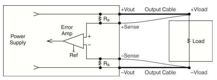
Simplified schematic of remote sense circuit with external output and sense wires
-
Why a switch or fuse shouldn’t be used on the output wires
On occasion, a switch or fuse may be installed in series with one or both output wires as an added safety mechanism. However, this can cause a serious problem if the remote sense lines remain connected to the load.
Why?
Because if the output cable switch or fuse opens, current will flow in the sense lines and cause the internal Rsense resistors to burn up.
System debugging can cause similar problems; for example, where the power and sense cables are located on separate connectors and if by error, only the power cable connector is disconnected.
Our videos are hosted by Vimeo.By viewing this content you are agreeing to the Terms & Privacy Policy laid out on the Vimeo website.
-
What to do if you are not using the remote sense feature
In cases where the remote sense feature is not used, the remote sense lines should not be left open for optimum load regulation; instead, a local sense configuration should be set up.
To set up a local sense circuit, the +ve and –ve sense lines should be either:
1. Connected to their corresponding local sense (LS) terminals, which are provided on many power supplies
2. Connected to their corresponding +Vout and –Vout terminals.
Most power supplies are shipped from the factory with local sense jumpers installed on the power supply, see red and black jumper wires on left image, or with sense screw terminals connected to the output screw terminals with metal jumpers, as shown on the right image.
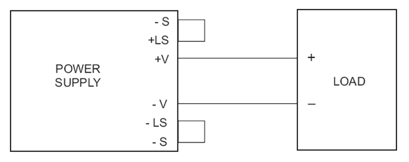
Schematic of power supply with ‘local sense’ jumpers installed
If you can't find what you're looking for then feel free to get in touch

