Alternatively, you can contact us like this:
This form is protected by Cloudflare and their Privacy Policy and Terms of Service apply.
Technical Centre
EMC/EMI Filters FAQ
Select question from the list below or return to faq categories.
-
How does an input EMI filter work?
Most electronics contains an EMI filter, either as a separate device, or embedded in circuit boards. Its function is to reduce high frequency electronic noise that may cause interference with other devices. Regulatory standards exist in most countries that limit the amount of noise that can emitted.
EMI, or Electro-Magnetic Interference, is defined as unwanted electrical signals and can be in the form of conducted or radiated emissions. Conducted EMI is where the noise travels along the electrical conductors and radiated EMI is where the noise travels through the air as magnetic fields or radio waves.
EMI is generated from the switching of electrical current and comes from a variety of sources including electronic power supplies. Power supplies convert an input voltage into regulated and isolated (in most cases) DC voltages to run a host of electronic components. That conversion is performed at high frequencies ranging from several kHz to more than a MHz. LED lighting, computers, motor drivers, DC relays and battery chargers all rely on power supplies to operate.
An EMI filter for a power supply normally consists of passive components, including capacitors and inductors, connected together to form LC circuits. The inductor(s) allow DC or low frequency currents to pass through, while blocking the harmful unwanted high frequency currents. The capacitors provide a low impedance path to divert the high frequency noise away from the input of the filter, either back into the power supply, or into the ground connection.
In addition to assisting to meet EMI regulations, the filter also has to meet safety standards. The inductor temperature rise is measured and for mains operation, the minimum electrical spacing between line, neutral and ground are controlled. This reduces the risk of fire and electrical shock. The capacitors are also individually safety certified, depending on their position in the circuit. Special “X” capacitors have to be used across the input terminals and “Y” capacitors from the AC circuit to ground.
Figure 1 shows a simple single stage power supply filter
-
How do I select an external EMI filter for use with a power supply?
Although most power supplies have an internal EMI filter, there are situations where an additional system filter is needed to comply with regulations. Power supplies are tested for the manufacturer by certification laboratories in optimum, repeatable conditions. Input and output cabling is well separated, and resistors used to load the product.
In reality, system space constraints for cabling, loads with fast switching microprocessors and/or the use of more than one power supply (EMI noise is additive) can generate additional noise. In this case an additional EMI filter may be needed.
Let us consider an application using TDK-Lambda’s SWS1000L-24 1000W power supply, and that the system will be operated on world-wide AC inputs of 115 or 230V.
The first parameter to consider is the input voltage. Common input voltage ratings are 250Vac or dc, 500Vac or dc (three phase) or 75Vdc. Note - a 250Vac filter can be used with 115Vac inputs. For the SWS1000L power supply, then we will need a filter rated at 250VAC.
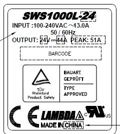
The current rating should then be determined. The power supply datasheet should state maximum input current, or alternatively on the rating label. The rating label for the SWS1000L-24 power supply is shown below. Note that the input current shown is for a worse case of 100Vac input and accounts for the power supply inefficiency and power factor. Never assume that a 1000W power supply will only draw 10A at 100Vac input!
See Fig 1
If the power supply is to be used only with a 230Vac input, then the filter rating can be reduced to approximately half. That information will provided on the datasheet.
Continuing with our SWS1000L-24 example, we will need a filter rated at a minimum of 16A to give us a 20% safety margin, as it is not good practice to operate parts at their maximum rating. Running a filter above its rated value, even for short periods, can cause the internal inductors to saturate and become ineffective.
From TDK-Lambda’s website selector guide the RSEN2016 looks suitable. Looking at the derating curve for 50oC ambient, we are within the specification.
see Fig 2
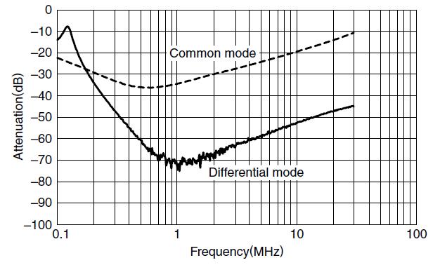
To see how effective the filter is, we then need to look at the attenuation characteristics on the datasheet.
See Fig 3
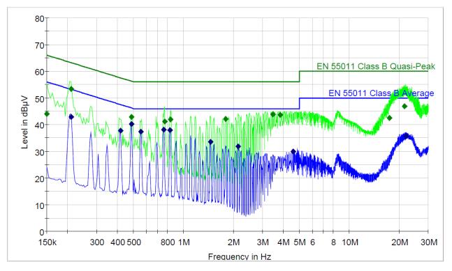
From the evaluation data on the SWS1000L-24 we can see what the EMI performance of the unit is. We can then check if the filter has a good insertion loss at any of the frequencies we want to reduce further, in this case 1-10MHz
See Fig 4
As the SWS1000L series has medical safety certifications, earth leakage current may be a consideration. The low leakage RSEN2016L should be used, as the RSEN2016 has 1mA leakage, compared to the L version’s 0.01mA.
Attenuation of the RSEN2016L is still good for the application.
see Fig 5
Further options are available for the TDK-Lambda R series if more attenuation is required. The RSHN2016L is a two stage filter with better performance (0.1mA leakage current).
See Fig 6
If input transients are a concern, the RSMN2016 or RSMN2016L filters feature a two stage filter design with an amorphous core to clamp any high voltages surges.
If it is desired to mount the filter on a DIN rail, then any of the above models can be ordered with a DIN rail clip, for example RSHN2016LD.
When taking a system to an external test house, TDK-Lambda advises bringing a selection of different performance filters. This avoids having to reschedule with the test house (at extra cost), and also minimise the filter cost. TDK-Lambda Technical Support can also assist with your design and give advice on cable routing and noise suppression.
SWS1000L-24 Rating Label

RSEN2016 Derating Curve

RSEN2016 Attenuation vs Frequency Characteristics

SWS1000L-24 conducted EMI plot

RSEN2016L Attenuation vs Frequency Characteristics

RSHN2016L Attenuation vs Frequency Characteristics
-
How to select a line filter to reduce input transients
In addition to EMI (Electro Magnetic Interference) reduction, some EMC line filters are able to provide protection against input transients. These external influences can come from a number of sources and their energy level (measured in Joules) varies accordingly.
High frequency noise is usually generated by power supplies and motor drives. The voltage level is small and the energy level minimal - only several mJ. This can be easily handled by a standard EMI/EMC filter.
Impulsive noise is generated from relay switching or induction motors. Voltages can be in the thousands of Volts with an energy level of hundreds of mJs, significant enough to cause problems with a power supply. Although the IEC 61000-4-4 standard covers product immunity to electrical fast transient voltages on the input lines, the test limits for this are only +/-2kV. For more noisy environments, a filter containing additional protection is recommended.
Surge noise is caused by lightning, and can have significant energy content. The voltage is very high, in the 10s of kVs. This level of energy is best clamped using special lightning arresters.
See Fig 1
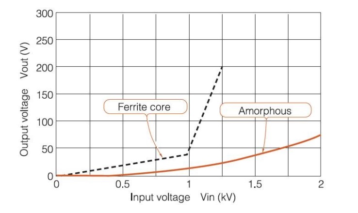
TDK-Lambda uses amorphous cores to reduce impulsive noise spikes, rather than metal oxide varistors (MOVs) or voltage dependent resistors (VDRs). MOVs clamp spikes, but degrade over time following multiple line surges. Amorphous cores are made from very thin (μm) ferromagnetic amorphous metal strips wound to form a doughnut shaped core, and do not degrade.
Although the ferrite cores used in most EMI/EMC filters do reduce the amplitude of voltage spikes, they can saturate and cause a significant decrease in attenuation.
Shown below is a comparison between a ferrite core and an amorphous core, and the test method used. It can be seen that the amorphous core out performs the ferrite core.
See Fig 2 & 3
TDK-Lambda’s R series filters that have amorphous cores for high voltage pulsed noise prevention can be found in this selector guide.
Models include:
RSAL 250VAC 0.5 to 6A General purpose
RSAN 250VAC 3 to 60A General purpose
RSMN 250VAC 3 to 60A Two stage filter for better performance
RTAN 500VAC 3 phase 6 to 60A General purpose
RTMN 500VAC 3 phase 6 to 60A Two stage filter for better performance
Power supply failure analysis reports often include independent laboratory test reports that state “component over voltage stress”. The reaction of the recipient is often one of disbelief, claiming that at the time of failure there was no abnormal AC line activity.
Without appropriate protection, input surges can damage a power supply over a long time period, with the effect not seen immediately. High voltage surges will stress and damage both semiconductors and passive components alike, leading to premature failure in the field.
Using a slightly more expensive EMI/EMC filter with pulse attenuation can improve system up-time and reduce expensive service calls.
Fig 1

Fig 2

Fig 3
-
What are the Safety Standards for EMI/EMC filters?
Safety standards for EMI/EMC are different than those used with power supplies. The International Electrotechnical Commission (IEC) has published IEC 60939-1, but as of March 2015, the standard IEC 60939-1 has not been formally adopted globally.
Europe has adopted the standard with EN 60939 - relating to “passive filter units for electromagnetic interference suppression for use within, or associated with, electronic or electrical equipment and machines”.
In the USA, UL 1283 is the standard – “requirements cover electromagnetic interference (EMI) filters installed on, or connected to, 1000 V or lower potential circuits, 50 - 60 Hz, or up to 1500V dc, and installed in accordance with the National Electrical Code”.
Even Canada with CSA C22.2 No.8 has a different standard – applying to “applies to filters intended for suppressing electromagnetic interference in, or with, apparatus and machines that are to be connected to an ac supply with nominal system voltages of up to 750V and a nominal frequency of up to 60 Hz or connected to a dc supply up to 1060 V dc, intended to be used in nonhazardous locations in accordance with the Canadian Electrical Code, (CEC) Part I”.
Canada and the USA are cooperating on safety certifications and the cULus recognised logo can be seen on filters along with the European certified test houses (TUV, VDE, NEMKO, SEMKO, DEMKO, ENEC and others).
What will not be present is the CE mark as filters are excluded from the current EU directives, as they are classified as components.
-
Are EMI and EMC filters the same thing?
There are a variety of terms used by manufacturers to describe their filters; they include “noise filters”, “EMI filters” and “EMI/EMC” filters. To best answer this question “are they the same thing?” we need to review the differences between EMI and EMC.
From a legislative viewpoint, EMI (ElectroMagnetic Interference) is the measurement and restriction, to defined limits, of unwanted conducted or radiated electrical noise from a product. Under this term, a power supply and/or the equipment it is powering is considered the “source”.
EMC (ElectroMagnetic Compatibility) immunity on the other hand is the ability to withstand, again to defined limits, a variety of external electromagnetic signals. Under this term, a power supply and/or the equipment it is powering is considered the “victim”.
Regulation of both the “source’s” emissions and the ability of the “victim” to function under those emissions (and other external influences), guarantees the end product a defined level of performance.
Regulation of conducted and radiated EMI in Europe is commonly defined by two standards. EN 55011 covers industrial, scientific and medical appliances and EN 55022 information technology and telecommunications equipment. The less stringent Class A level is used for industrial and Class B for medical and household applications.
See Fig 1
Regulation of EMC immunity in Europe is defined by EN 61000, which is a very broad set of standards. For the purpose of this article, only the two sections applicable to a typical EMI/EMC filter used with a power supply will be discussed.
EN 61000-4-4: Electrical fast transient/burst immunity test – here bursts of electrical noise are injected on the input lines to simulate inductive switching, relays, etc.
EN 61000-4-5: Surge immunity test – here single pulses are injected on the input lines to simulate lightning strikes and high energy switching.
It should be noted that both of the above sections include different test voltages (ranging from 500V to 4,000V peak) and different performance criteria. With criteria A the product will continue to operate as normal during the test, B states a recovery after the test, C requires user intervention to restart the product and D is a loss of function that is not recoverable.
Certainly any filter with suitable attenuation characteristics will reduce EMI and can to some extent improve EMC immunity due to their inductive and capacitive content.
Filters like TDK-Lambda’s RSAL and RSMN series contain amorphous cores that attenuate the bursts and pulses described in the EMC immunity EN 61000-4-4 & -5 sections and allow the product to be compliant. (see FAQ “Selecting a line filter to reduce input transients”)
Are EMI and EMC filters the same thing? Yes, although actual product EMC immunity performance will depend on the filter characteristics, the test voltage level and the desired performance criteria.
Conducted EMI Plot (level B) for TDK-Lambda’s Medical ZMS100 power supply
-
How to Specify Low Leakage Current EMI/EMC Filters for Power supplies
Leakage current is the current flowing through the earth ground connection. This current may be generated not only by the AC-DC power supply or supplies, but also from any additional external line filtering used to further reduce electrical noise.
Most manufacturers of power supplies use “Y” capacitors connected from the line and neutral to ground as part of their integral EMI filter. These specially rated capacitors provide a low impedance path to the ground for high frequency noise to reduce EMI. The larger those “Y” capacitors are, the lower the measured noise.
See Fig1
There are, however, limits for maximum leakage current put in place by the safety standards for electrical and electronic equipment. That limit depends on the application and what ground connection is used. Medical, because sick patients are more vulnerable to electric shock, is the most stringent. Below are the limits for the most common applications.
IEC 60950-1 Information Technology Equipment
Handheld 0.25mA
Moveable (not handheld) or pluggable 3.5mA
Permanently connected 3.5mA (or higher for some applications)
IEC 60601-1 Medical (Body Float – B category)
Portable 0.5mA Europe 0.3mA in USA
Let us assume we are designing a portable piece of medical equipment to be used globally, thus our leakage current “budget” is 300μA. We are also going to assume that we may need an additional external filter because of some additional system noise.
For our power supply we have chosen TDK-Lambda’s EFE300M series and from the datasheet it says that the leakage current is 246μA at 240Vac (60Hz).
According to the manufacturer, the input current rating of the EFE300M is 6.1A. We have a choice of TDK-Lambda filters in the 10A range, allowing for some filter derating.
See Fig 2
From the filter datasheets:
Filter Low Leakage Version Normal Leakage Version
RSEN-2010 10μA at 250VAC 1mA at 250VAC
RSHN-2010 100μA at 250VAC 1mA at 250VAC
RSAN-2010 10μA at 250VAC 1mA at 250VAC
RSMN-2010 100μA at 250VAC 1mA at 250VAC
The two filters that we can use are the RSEN-2010L or the RSAN-2010L with a leakage current of just 10μA at 250VAC. We cannot use a filter with a higher leakage current as the power supply leakage + the filter leakage will be greater than 300μA.
As this is a hospital environment, we can probably go with the RSEN-2010L without spike pulse attenuation. A look at the attenuation characteristic plot shows we will have a good margin for the application and will not need a higher performance two stage filter.
See Fig 3
A look at the datasheet for the RSEN-2010L shows that there are no Y capacitors between line/neutral and ground, hence the filter design has very low leakage.
See Fig 4
One note of caution - a two power supply scenario is quite common. Often the leakage current budget will be affected by an ATX PC power supply driving a computer, or a power supply driving the flat panel display. A good piece of advice is to always check the system block diagram to see where the AC input is being routed to!
Fig 1

Fig 2

Fig 3

Fig 4
If you can't find what you're looking for then feel free to get in touch

