U kunt ook op de volgende manier contact met ons opnemen:
Technisch Expertisecentrum
AC-DC voedingen FAQ
Kies een vraag uit de onderstaande lijst:
-
Wat zijn de nieuwste AC-DC Power Brick oplossingen?
Power Supply manufacturers have not stopped developing smaller and better power solutions. In fact, in recent times the AC/PFHC brick mentioned above has been merged with a DC-DC converter to form the ultimate power solution; an AC/PFHC/DC integrated brick. These 2-in-1 devices accept wide range 85 to 265 VAC inputs, correct the power factor, and provide the DC output(s) to the system. All this is accomplished within the same size constraints of a single “full brick” package measuring only 2.4” W x 4.6” L x 0.5” H, thus providing a 50% board space savings (Figure 3).
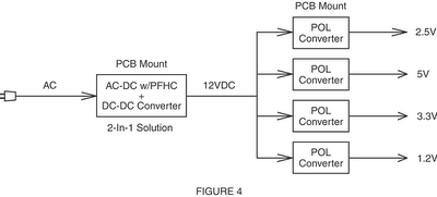
These integrated 2-in-1 PCB-mounted Power Bricks are ideal for Distributed Power Architectures where POL (Point of Load) Converters are needed. Since the 2-in-1 Power Bricks provide the conversion from AC to DC (with PFHC) along with the needed isolation, and the Intermediate Bus Voltage, the use of multiple low-cost, non-isolated POL converters becomes quite practical (Figure 4).
Recent advances in components and power design technologies have made these new 2-in-1 PCB-mount power bricks possible. In order to increase power densities, special Permalloy cores have been developed and employed in the inductors. New substrates and innovative transformer winding techniques have facilitated component height compressions and improved thermal management. And, of course, advances in integrated and hybrid circuits have contributed greatly to this next generation of power products.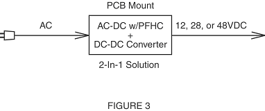
-
Wat is een 2-in-1 AC-DC Power Brick?
TDK-Lambda manufacturers a range of integrated “single-brick” AC-DC power bricks. These “2-in-1” PCB-mount devices are so innovative, they have seven patents pending. Some of the salient features of TDK-Lambda's single-brick AC-DC PFE series (/uk/pfe) power modules include:
- Operates from Universal 85 to 265Vac, 47-63Hz Input
- Power Factor & Harmonic Correction Meets EN61000-3-2
- Low Profile, Single-Brick Footprint
- High Power Density (up to 129W/in3) & Efficiency (up to 90%)
- Regulated and Isolated DC Outputs with Wide Operating Temperatures (at baseplate)
- PFE500-12: 12VDC Output, 400 Watts, -40 to +85°C
- PFE500-28: 24 to 28VDC Output, 500 Watts, -40 to +100°C
- PFE500-48: 48VDC Output, 500 Watts, -40 to +100°C
- PFE700-48: 51VDC Output (semi-regulated), 714 Watts, -40 to +85°C
- ±20% Output Voltage Adjustment Range
- Over Voltage/Current/Temperature Protection
- Approved to UL/CSA/EN60950-1, CE Marked, & RoHS Compliant
- Optional Heat sinks & Evaluation Kits Available
-
Wat zijn typische toepassingen voor 2-in-1 AC-DC Power Brick’s?
These new "2-in-1" AC-DC power bricks are ideal for many outdoor and indoor applications including:
- Custom Power Supplies
- PCB Mounted Bulk Power for Multiple DC-DC or POL Converters
- Large LED & Liquid Crystal Displays
- Traffic Information, Control, & Signalling Equipment
- Toll Devices
- Pico & Cell Phone Repeaters
- WiFi, Telecom Sub-Stations
- Underwater Surveying Devices
- Automatic Pass-Reading-Devices for FastTrac Car Lanes
- Oil Pumping & Pipeline Monitoring Devices
- Security Systems
-
Kan mijn AC-DC voeding ook op gelijkspanning werken?
...The answer is yes, sometimes. But the unit's safety certification may only apply to AC input.
Many standard AC-DC switched mode power supplies (most of TDK-Lambda’s products) will operate from voltage DC input range in addition to the more common AC input range of 90-264VAC.
However we strongly recommend users to contact their supplier for guidance on safe installation.
-
In welke situaties en waarom wordt gebruik gemaakt van hoge DC-ingangsspanningen?
It turns out that many power generation facilities provide a high voltage DC to power the plant's equipment rather than the regular 115Vac or 208Vac power grid. This high voltage DC (typically 120 or 130-330Vdc) can be easily used with batteries to provide a secure source of power rather than using expensive centralised or local UPS systems.
Now back to the subject. The topology of many switched-mode power supplies actually lends itself to operation from either AC or DC input. Important Note: Always check your power supply’s Operations Manual or spec sheet to confirm that it is designed to operate from either an AC or DC input.
Referring to the simplified power supply schematic below:
When powered by an AC sine wave, during the first half cycle the current flows from the Line terminal through the input filter and charges capacitor C1 through diodes D1 and D3. During the second (negative) cycle, current flows from the Neutral terminal and capacitor C1 is charged through diodes D2 and D4.
When powered from a high voltage DC source, the polarity of the connection is not critical as far as the operation of the power supply is concerned. If the positive connection is made to the Line terminal, C1 is charged through diodes D1 and D3. If the positive connection is made to the Neutral terminal, then C1 is charged through diodes D2 and D4.
An important note of caution to insert here is about the protective fusing of the power supply. Safety certifications of the power supply may only apply to AC operation and should be checked carefully. Internally most power supplies have a fast acting AC rated fuse in series with the Line terminal. It is not accepted by UL for a DC rated fuse be installed external to the power supply.
In order to comply with Safety Agency requirements, the internal fuse must be suitably rated for DC. It is recommended that you consult with your supplier for advice.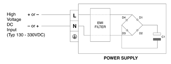
-
Wat zijn de trends in de ontwikkeling van voedingen?
Linear power supplies were the mainstay of power conversion until the late 1970’s when the first commercial switched-mode power supply became available. Now switched-mode power supplies are dominant driven by market demand for miniaturisation and high efficiency levels.
-
Wat zijn de verschillen tussen lineaire en schakelende voedingen en wat is hun werking?
Linear power supplies have a bulky steel or iron laminated transformer. It provides a safety barrier between for the high voltage AC input and the low voltage DC output. The transformer also reduces and the AC input from typically 115V or 230Vac to a much lower voltage, perhaps around 30Vac. The lower voltage AC is then rectified by two or four diodes and smoothed into low voltage DC by large electrolytic capacitors. That low voltage DC is then regulated into the output voltage by dropping the difference in voltage across a transistor or IC (the shunt regulator).
Switched-mode power supplies are a lot more complicated. The 115V or 230Vac voltage is rectified and smoothed by diodes and capacitors resulting in a high voltage DC. That DC is then converted into a safe, low voltage, high frequency (typically switching at 200 kHz to 500 kHz) voltage using a much smaller ferrite transformer and FETs or transistors. That voltage is then converted into the DC output voltage of choice by another set of diodes, capacitors and inductors. Corrections to the output voltage due to load or input changes are achieved by adjusting the pulse width of the high frequency waveform.
-
Wat zijn de overeenkomsten tussen lineaire en schakelende voedingen?
Size – A 50W linear power supply is typically 3 x 5 x 5.5”, whereas a 50W switched-mode unit can be as small as 2 x 3 x 0.9”. That’s a size reduction of over 90%.
Weight – A 50W linear weighs 4lbs (1.8kg); a corresponding switched-mode unit is 0.22lbs (100g) or less. As the power level increases, so does the weight. I personally remember a two-man lift needed for a 1000W linear power supply!
Input Voltage Range – A linear power supply has a very limited input range requiring that the transformer taps be changed between different countries. Normally on the specification you will see 100/120/220/230/240Vac. This is because when the input voltage drops more than 10%, the DC voltage to the shunt regulator drops too low and the power supply cannot deliver the required output voltage. At input voltages greater than 10%, too much voltage is delivered to the regulator resulting in over heating. If a piece of equipment is tested in the US and shipped to Europe, or even to Mexico in some cases, the transformer “taps” have to be manually changed. Forget to set the taps? The power supply will most certainly blow the fuse, or may well be damaged.
Most switched-mode power supplies can operate anywhere in the world (85 to 264Vac), from industrial areas in Japan to the outback of Australia without any adjustment. The switched-mode supply is also able to withstand small losses of AC power in the range of 10-20 milliseconds without affecting the outputs – a linear power supply will not. No one will care if the AC goes missing for 1/100th of a second when charging your cell phone, it will take 100 of these interruptions to delay the charge by one second. However, having your computerised equipment shutdown or reboot 100 times a day will cause a great deal of heartburn.
Efficiency – A linear power supply because of its design will normally operate at around 60% efficiency for 24V outputs, whereas a switched-mode is normally between 85% and 95%. Efficiency is a measure of how much energy the power supply wastes. This has to be removed with fans or heat sinks from the system. For a 100W output linear running at 60%, that waste would be 67W. A 100W switched-mode power supply running at 90% efficiency would be just 11W. Therefore, (67W – 11W) 56W is the extra power lost by a linear supply. Doesn’t sound much, but don’t try touching a 40W light bulb.
-
Is er nog een toekomst voor lineaire voedingen?
Only in a few specialist applications – energy saving legislation, such as ErP, EISA and CEC, coupled with remorseless miniaturisation trends of electronic equipment means that linears will only be niche in the future.
-
Waarom is de ingangsspanning van mijn voeding gespecificeerd op slechts 100 tot 240 VAC?
Most power supplies have a rating label that looks something like this:
INPUT: AC 100V-240V~ 50 / 60 Hz
However, a close look at the power supply’s datasheet will usually show the absolute AC input voltage range, from minimum to maximum. This is usually 90-264Vac, or 85-264Vac if the power supply has been designed for use in Japan.
Parts of Japan use the lowest AC mains voltage, which is 100Vac nominal; however, short duration AC line droops or brown-out conditions often mandate a rating down to 85Vac. The UK is among the countries that use the highest AC mains, with a nominal rating of 230Vac +10% -6%.
The safety certification bodies (UL, CSA, TUV, etc.) mandate that a rating of 100-240Vac be listed on the power supply's label. However, they factor in a +/-10% tolerance for the power generation and transmission utilities. -10% of 100VAC is 90Vac, and +10% of 240VAC is 264Vac. All safety testing is performed at the high and low limits as listed on the power supply's datasheet.
So, if the power supply label states 100-240Vac, it can usually operate over a wider AC operating input range. However, always check with the manufacturer's datasheet to confirm this. Continuous operation of the power supply over the datasheet’s specified AC input range will not normally cause any problems. In some cases, however, the maximum output power (total watts) of the power supply may need to be derated if the supply is operating off an input voltage that is on the low-end of the specified range. Always check the power supply's datasheet for the specified minimum AC input voltage with various output load levels. Deratings may also apply depending upon the power supply's operating ambient temperatures.
Should a label state 100/240Vac (note the slash) it "may" indicate that there is a voltage select switch or jumper that is required to be set for the correct operating input voltage range. Newer products tend to not have an AC select switch or jumper.
Worldwide, the AC mains power has a nominal frequency of either 50 or 60 Hz (cycles per second). However, these frequencies are subject to variations by the power generators in different countries (especially third world) and so the typical AC frequency range for power supplies is 47-63Hz.
-
Wat betekent PFC en waarom heb ik dat nodig?
Power Factor (PF) is technically the ratio of real power consumed to the apparent power (Volts-RMS x Amps-RMS), and is expressed as a decimal fraction between 0 and 1. PF is traditionally known as the phase difference between sinusoidal voltage and current waveforms. When the AC load is partly capacitive or inductive, the current waveform is out of phase with the voltage (Fig. 1, the dotted line is the current waveform). This requires additional AC current to be generated that isn't consumed by the load, creating wasted I2R (wattage) losses in the power lines.
An electric motor is inductive, especially when it is starting. The current waveform lags behind the voltage waveform, dropping the PF to well below 1 (similar to Fig. 1). This is why many motors have "starting" capacitors installed to counteract the inductance, and therefore correct the PF during motor start-up.
A simple resistive load has the highest PF of 1. An AC voltage across the resistor causes an AC current which is identical to and in-phase with the voltage waveform (Fig. 2).
A switch mode power supply when viewed as an AC load is neither capacitive nor inductive, but non-linear. A switch mode supply conducts current in short pulses or spikes that are in-phase with the line voltage (Fig. 3). The product of "Volts-RMS x Amps-RMS" is considerable higher than the real power consumed, and thus the PF is much less than 1, typically around 0.65 or less.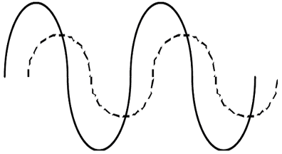
Fig. 1: Voltage and current waveforms are sinusoidal but out-of-phase; PF<1
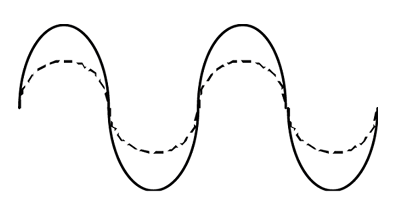
Fig. 2: Voltage and Current waveforms are sinusoidal and in-phase; PF=1
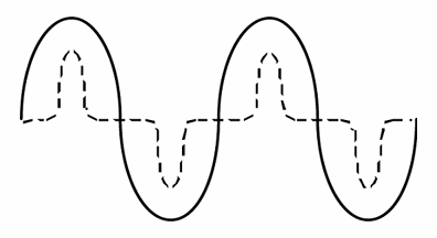
Fig. 3: Voltage waveform is sinusoidal, current waveform is non-sinusoidal but in-phase; PF<1
-
Hoe kies ik de juiste EMI-ingangsfilter voor mijn voeding?
There are two primary functions that an input EMI filter can perform:
1. Minimize outgoing electrical noise to avoid interfering with neighbouring equipment 2. Attenuate (reduce) incoming electrical noise that could damage the system
Regarding outgoing noise, although most power supplies meet the governmental regulations for EMI, noise is additive and if there are multiple power supplies or high speed processor boards, it can result in a failing grade.
If the noise is only slightly out of specification, then a (lower cost) single stage filter may suffice. If the noise is considerably out of specification then a higher performance two stage filter will be required.
An example of these would be TDK-Lambda’s MA (single stage) and MX (two stage) filters. Look for the terms “wideband” or “low frequency attenuation” in the features.
Incoming electrical noise is usually in the form of a spike or burst of energy. It can be generated from natural causes such as a lightning storm or man made by a large piece of industrial equipment.
This type of filter may have “high pulse attenuation” listed as a feature and will have internal values optimized to reduce these potentially harmful spikes from reaching the power supply. The filter will also have some outgoing noise attenuation, but may not be as effective. An example would be TDK-Lambda’s MZ series of filters.
Indien u niet kunt vinden wat u zoekt, neem dan gerust contact op.

